Circular Microstrip Patch Antenna Calculator
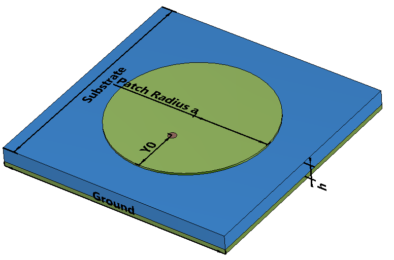
The dimensions of circular patch antenna is calculated for the dominant \(TM_{110}^{z} \) mode, where \(z\) is the vector perpendicular to the circular patch. The substrate the height \(h \) is much smaller than the resonant wavelength \(\lambda \). The ground plane is assumed to be infinite and all the metallic surfaces are lossless. Due to the fringing of fields the electrical size of the circular patch is larger than its physical radius \(a\) and it is calculated as \(a_e \).
Formula
\(a=\frac{F}{\left \{ 1+\frac{2h}{\pi\epsilon_rF}\left [ ln(\frac{\pi F}{2h}+1.7726 ) \right ] \right \}^\frac{1}{2}}\)
\(F= \frac{8.791e^9}{f_r\sqrt{\epsilon_r}}\)
\(a_e=a{\left \{ 1+\frac{2h}{\pi a \epsilon_r}\left [ ln(\frac{\pi a}{2h}+1.7726) \right ] \right \}^\frac{1}{2}}\)
\(D_{0}=\frac{(k_{0}a_{e})^{2}}{120G_{rad}}\)
\(G_{rad}=\frac{(k_{0}a_{e})^{2}}{480}\int_{0}^{\pi/2}\left [J_{02}^{'2}+cos^{2}\theta J_{02}^{2} \right ]sin \theta d \theta\)
\(J_{02}^{'}=J_{0} (k_{0}a_{e}sin \theta)-J_{2} (k_{0}a_{e}sin \theta)\)
| Where: |
| \(f_r \) = Resonant Frequency of Circular Patch Antenna |
| \(\epsilon_{r}\) = Substrate Relative Permittivity |
| \(h\) = Substrate Height |
| \(a \) = Physical Radius of the Patch |
| \(a_e \) = Effective Radius |
| \(D_{0} \)= Maximum Directivity of the Circular Patch Antenna |
| \(G_{rad} \) = Conductance across the gap between the patch and the ground plane |
| \(J_{0}\) = Bessel function of the first kind of order 0 |
| \(J_{2}\) = Bessel function of the first kind of order 2 |
Reference:
- [1] Balanis, C.A. (2016). Antenna Theory: Analysis and Design. 4th ed. Hoboken, New Jersey Wiley, pp.814–823. Chapter 14.3 Circular Patch.
Other Related Calculator:
-
Microstrip Rectangular Patch Antenna Calculator